Summary
The knobbox is a USB knob in a wood box. The boxes come in several shapes and sizes, while the internal hardware comes in two forms:
Electronics
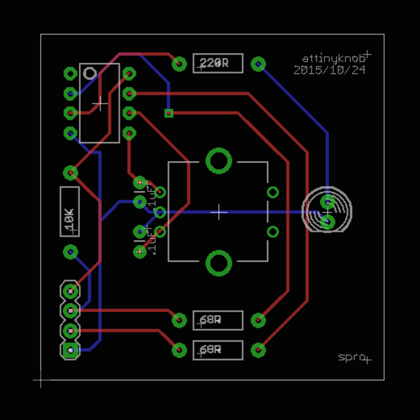
tinyknob (attiny85 with no crystal)
The simplest knobbox acts as a USB keyboard with two buttons: volume up and volume down. The hardware to achieve this is very minimal: a rotary encoder, status LED, and ATTiny85; a few resistors to meet USB voltage specs, and 47nF capacitors to filter noise from the encoder.
The ATTiny85 is great for small USB devices because it doesn't require an external crystal (the internal PLL clock can give you a rough 16MHz). Unfortunately all 5 usable pins are occupied already — two for USB data lines, two for the encoder, and one for the status LED. No more pins left, not even for the rotary encoder's built-in button, without disabling the reset pin (which is inconvenient for prototyping).
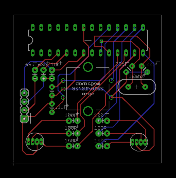
megaknob (atmega328p with 16MHz crystal)
The megaknob has the same basic shape with some enhancements. I replaced the 8 pin ATTiny85 with a 28 pin ATMega328P, added a crystal, changed the status LED to a RGB LED, and added another RGB LED for balance and good measure. Once I figured out how to make the trace lines thinner I was able to fit it all in the same footprint.
Having 20 extra pins opens the possibility of using the rotary encoder button, the basis of the "modal" aspect. Pressing the knob switches to the next of 8 modes, each with a corresponding color shown by the RGB LEDs. Turning the knob then does something different depending on the mode - defined by the driver software below.
Both PCBs are 1.75" (44.5mm) square and fit in any knobbox v2 or above. The rotary encoder can be mounted on the opposite side (with a small tweak to the firmware) side in case vertical space is an issue. Both were fabricated by OSHPark.
Software
tinyknob
The tinyknob software is as simple as the hardware: it registers itself as a USB HID keyboard, and each step of the knob sends a key code for volume up or down. The status light blinks to confirm the USB connection and stays on while in use.
megaknob
megaknob started off with a similar HID approach, where each press of the knob button would toggle modes, and each mode would have a status color and a set of keys to send (e.g. blue: volume, yellow: brightness). I quickly ran into limitations, specifically that there are no screen brightness keys in the official HID spec. Trying to emulate an Apple keyboard to use their brightness keys seemed possible, but troublesome. I went for the next best approach: a custom USB device driver.
The driver uses IOKit to watch for the device attaching and poll for messages while the device is attached. The megaknob sends a two byte status message every time something happens: one byte for the "mode" (incremented by pressing the knob) and one byte for the "value" (incremented and decremented by turning the knob).
The driver looks at the current mode to respond appropriately to the value change. Currently there are only two useful modes: blue for volume, and yellow for screen brightness. Future versions of the driver will let you change mode mappings outside of the code.
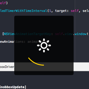
Alongside the driver are an overlay and status bar item that display current the mode and value in a friendly way.
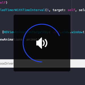
This driver approach is ultimately more flexible, but less plug-and-play ready than the HID approach.
Boxes
All iterations of the knobbox box were laser cut from 5.7mm walnut veneer MDF from Ponoko.
knobbox v1
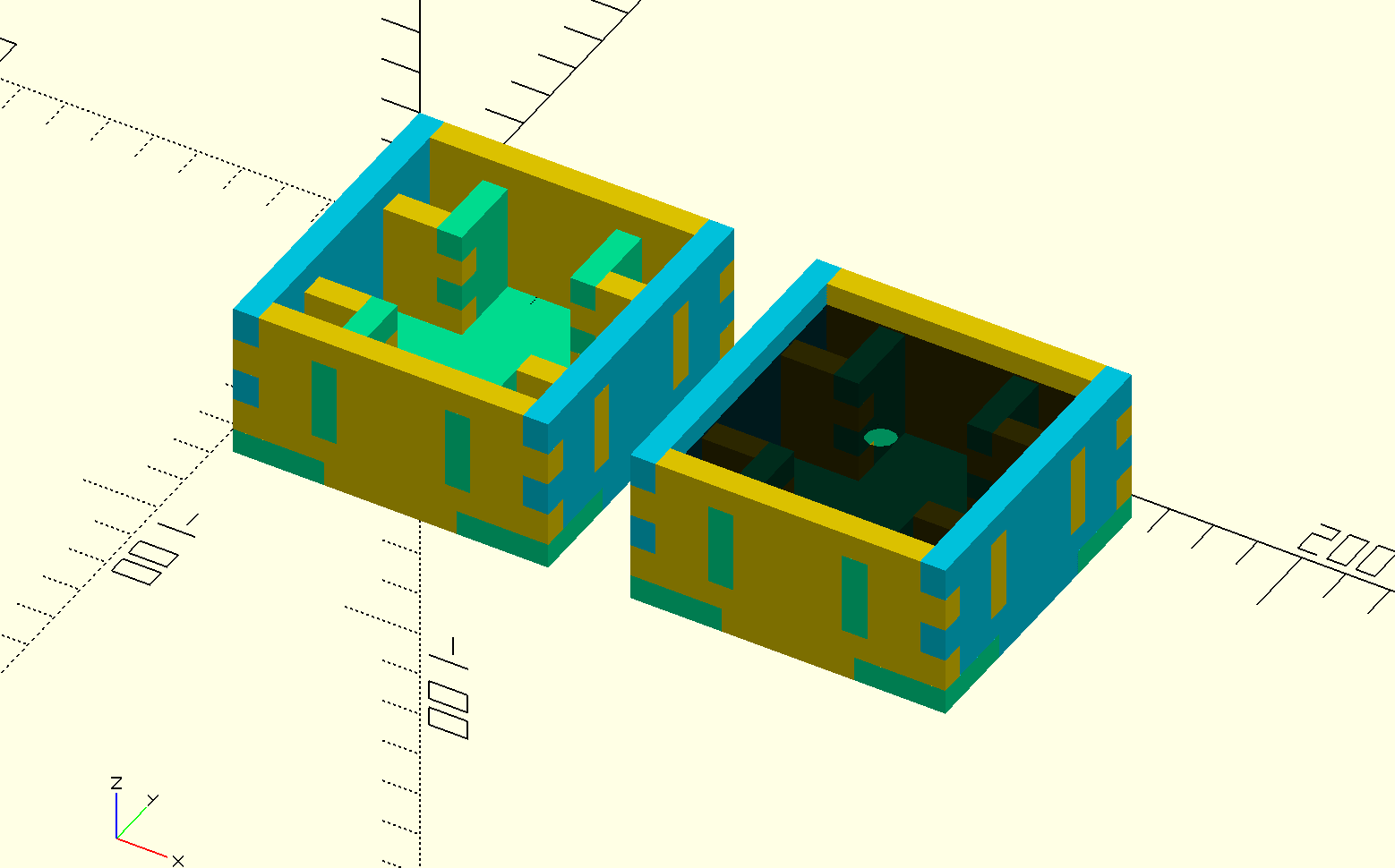
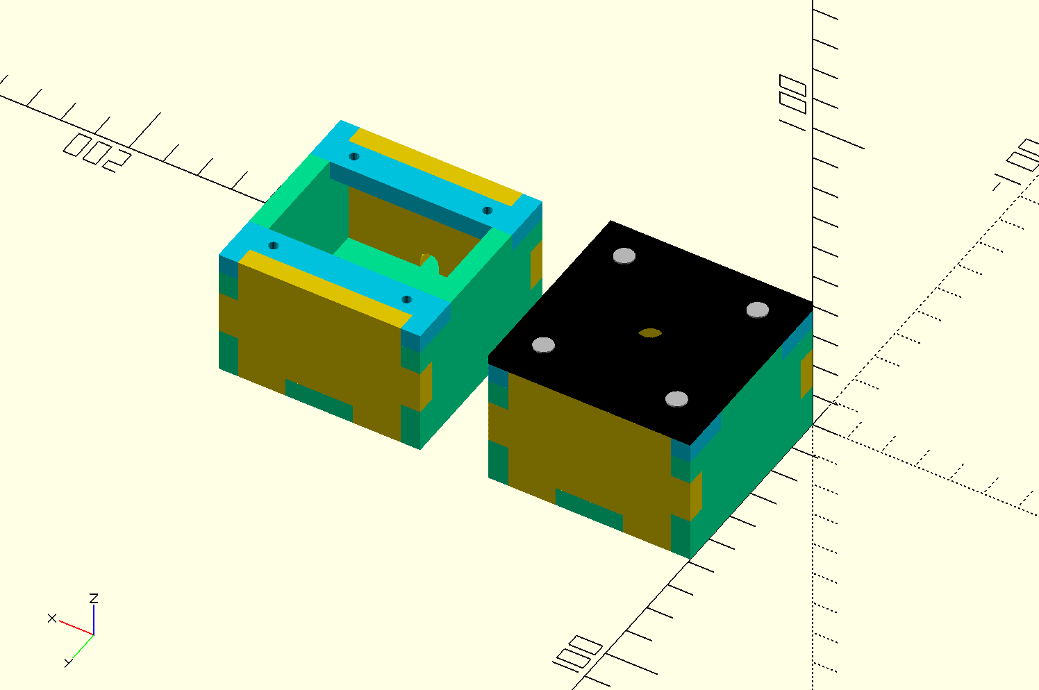
The first box started as an isometric vector drawing in Sketch. The design was re-implemented and improved in OpenSCAD, then flattened and exported to SVG for layout in Inkscape.
After going through the process a few times I wrote a build script that prepares the SVG for Ponoko's desired line widths and colors (0.01mm blue lines).
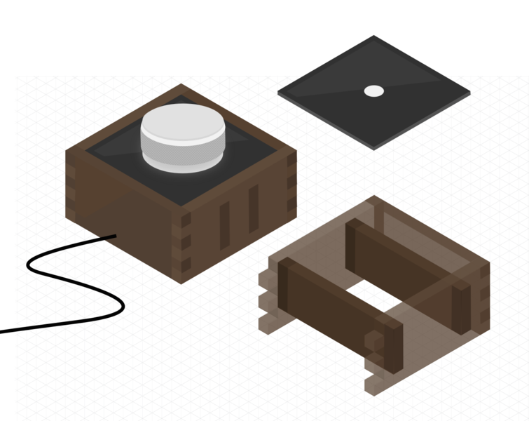
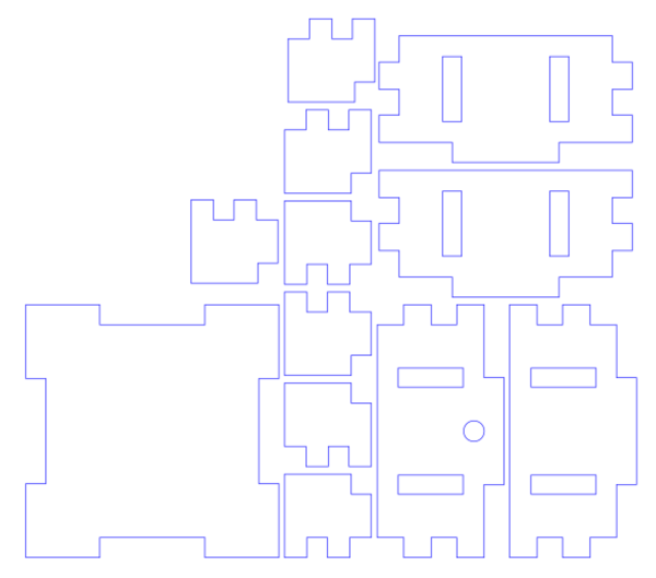
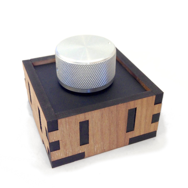
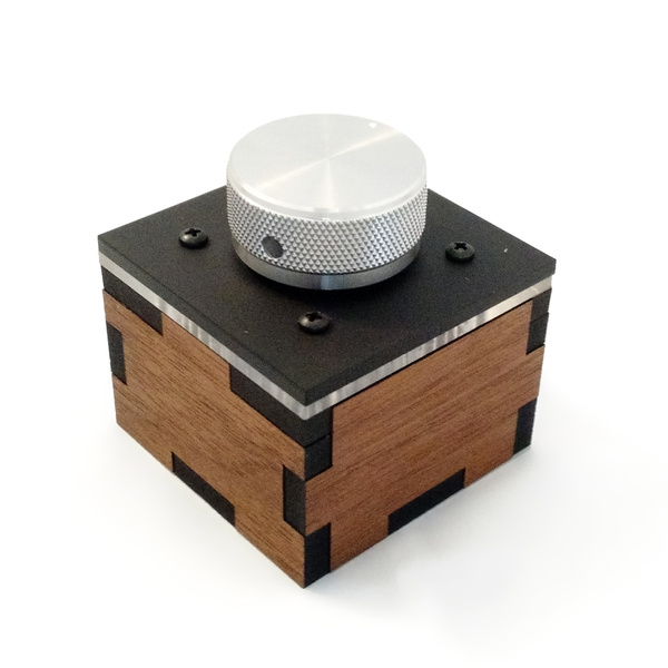
knobbox v1 has a "floating" acrylic panel (laser cut from black matte acrylic) supported by interlocking inner walls. The acrylic has a 7mm hole to mount the rotary encoder and knob.
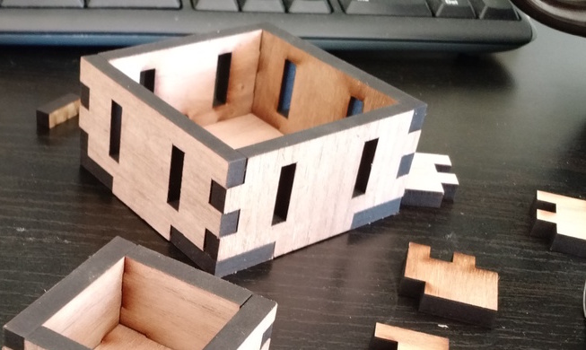
This box turned out very hard to assemble because I over-adjusted for laser kerf (offsetting the edges to compensate for the material burned away). The inner walls also made it pretty difficult to stuff a circuit board in there, especially a messy protoboard, so in the end only half of the inner pieces were used.
knobbox v2 (knobbox jr) & knobbox v3
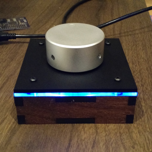
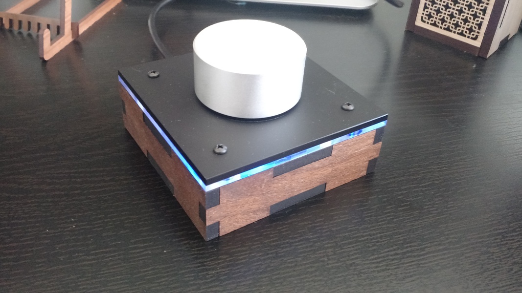
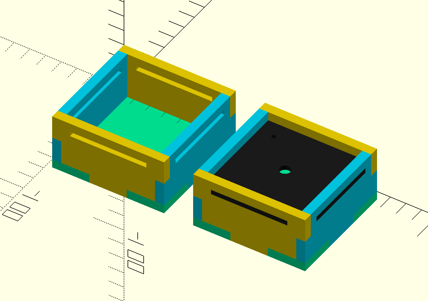
The inset acrylic of knobbox v1 looks nice, but is not sturdy. It's held in place by gravity and a bit of friction. knobbox v2 and knobbox v3 have a more secure arrangement: hollow tops with mounting holes for four 4-40 bolts, and corresponding mounting holes in the acrylic, which extends to the edges. Both were again laser cut from walnut veneer MDF.
knobbox v2 is a small, stout box that was optimized to fit exactly 2 boxes on one 181mm square panel of material (the P1 size from Ponoko). knobbox v3 is larger with a sleeker low profile.
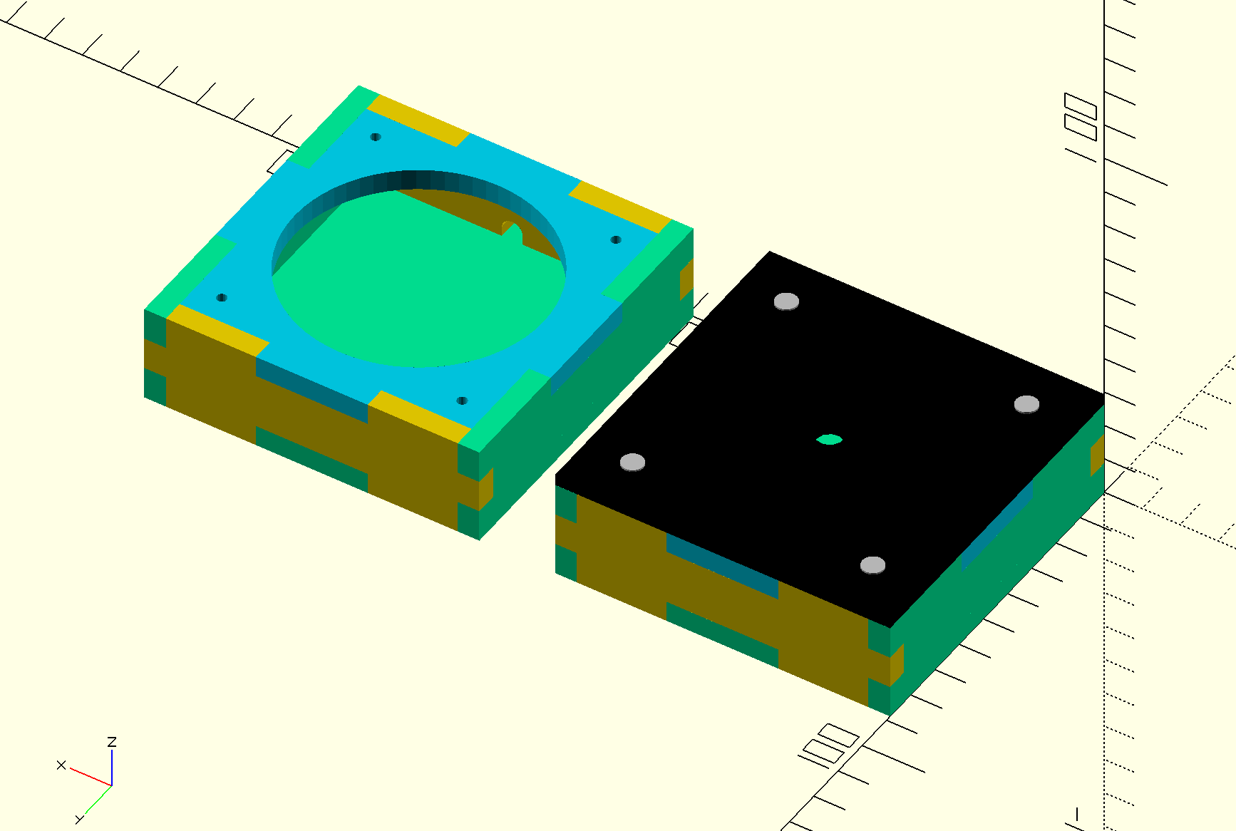
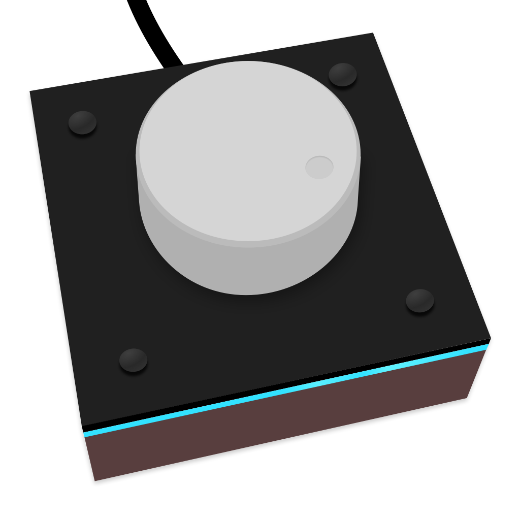
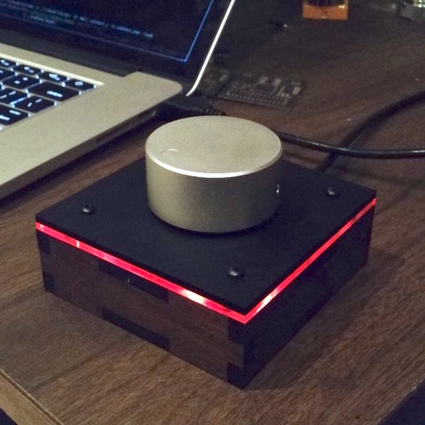
While prototyping the tinyknob circuit I enjoyed the effect of the blue status light spilling from the box. Wanting to harness this, I imagined a glowing rim enabled by the "edge lighting" effect of shining a colored LED through clear acrylic. I cloned the lids, cut a circle from the center (to make room for the circuit board), and had those laser cut in clear acrylic to be sandwiched under the matte black acrylic lid.
It worked out well:
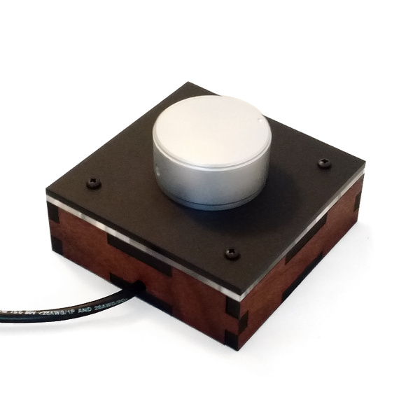
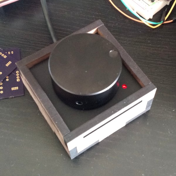
knobbox v4
The latest knobbox is a nod to the knobbox v1, using the same dimensions and a similar inset. Instead of a glowing rim this lid simply has a hole cut out to show the status light. The inset lid is attached to the rest of the box with a technique similar to the viewbox — tabs into slots in the surrounding walls.
Materials
- Rotary encoder (especially the Bourns PEC11)
- Debouncing capacitors (47nF on the encoder, 0.1uF on the button)
- Resistors (68R on D+ and D-, 10K pullup on D-, 150R for LEDs)
- ATTiny85 (tinyknob) and ATMega328P (megaknob)
- 16MHz crystal (+ 22pf capacitors) for megaknob
- Regular LED for tinyknob
- RGB LEDs for tinyknob
- Male to male USB 2.0 cables, cut in half
- Dupont crimp housing for stripped USB cables
- Aluminum knobs in various sizes, ordered from China
- Laser cut 5.7mm walnut veneer MDF from Ponoko
- Laser cut 3mm matte black acrylic
- Laser cut 3mm clear acrylic (for knobbox v2 and knobbox v3 edge effects)
- #4-40 nuts and bolts (for knobbox v2 and knobbox v3)
- Minimax wood stain and polyurethane
Inspiration
- The original V-USB volume knob, µVolume: Attiny84 V-USB Media Volume Control
References
- The USB HID code is copied from the V-USB example EasyLogger with improved calibration code copied from a Code and Life tutorial.
- Key codes for media keys (
0x80is volume up,0x81is volume down) were found in this USB HID usage table.